Ferrari 250 GTO Tutorial & Reflection

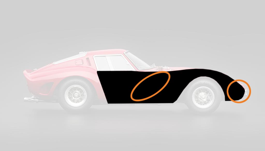
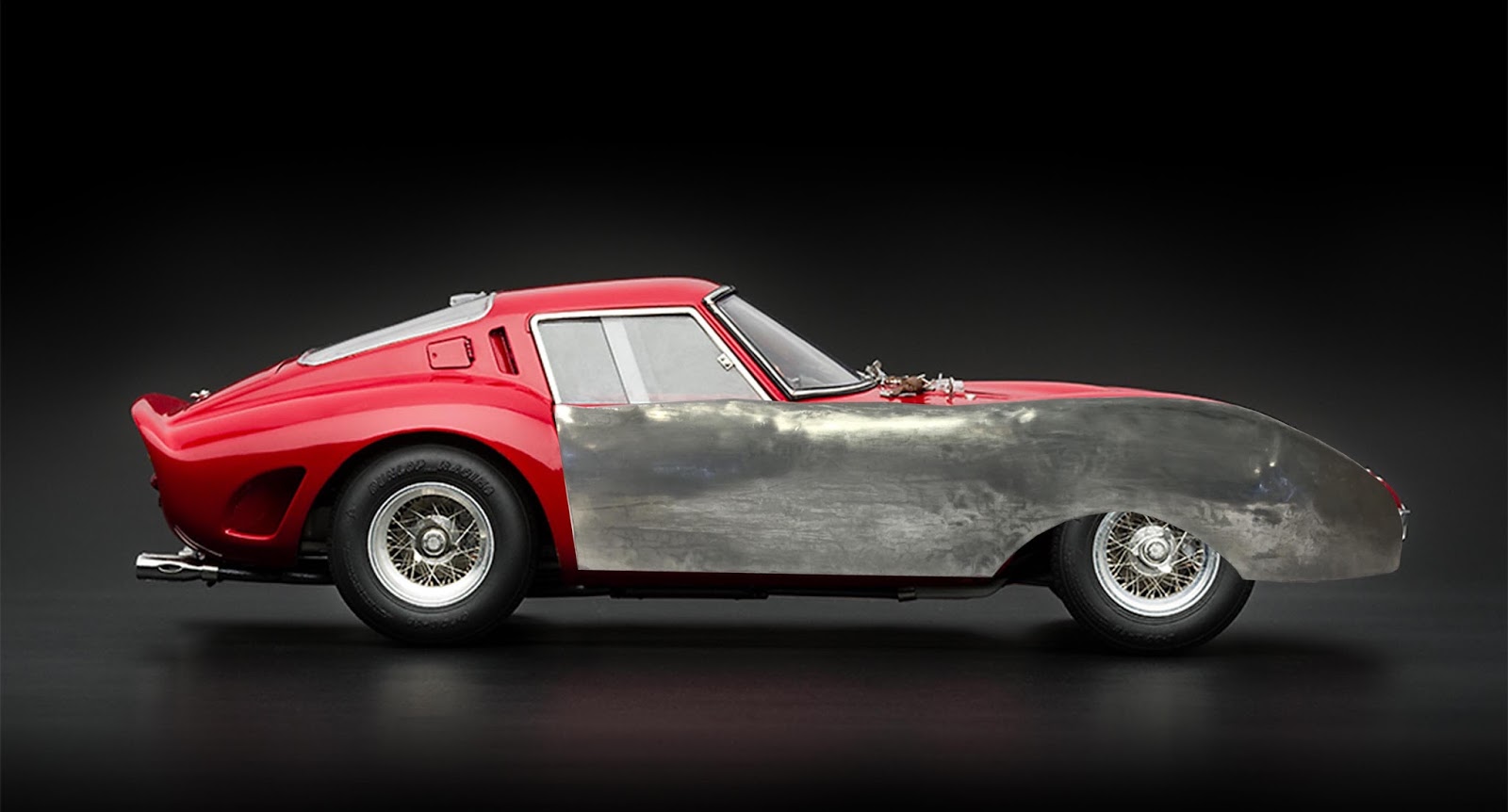
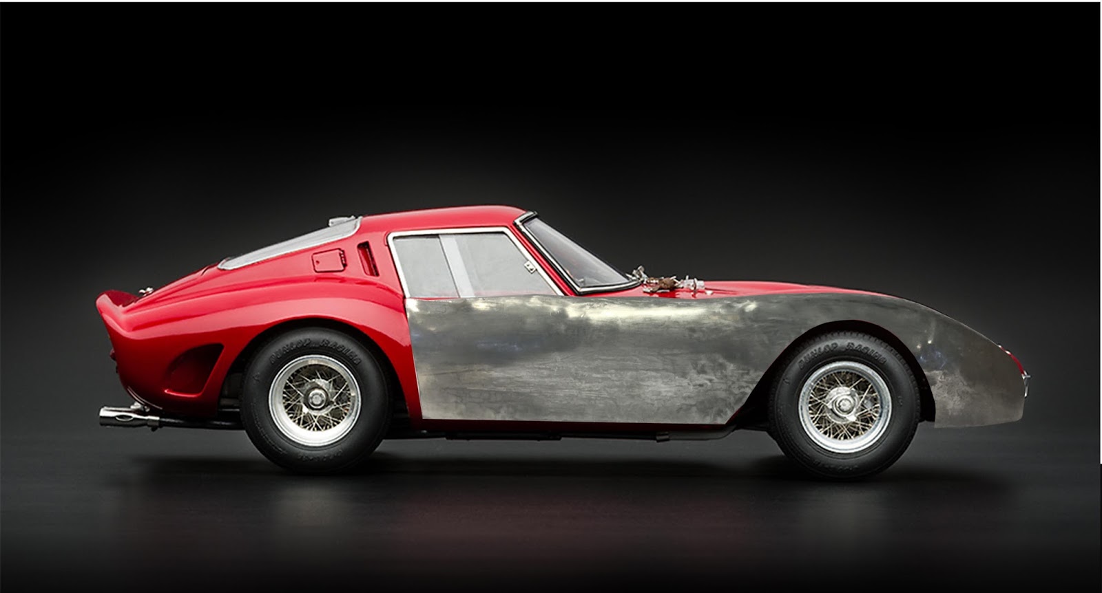
This tutorial will cover the group and individual processes undertaken to create a scale model aluminium skin of a Ferrari 250 GTO (pictured above).
The first task is to create a 'buck'.
A buck is the mould, or skeleton that the aluminium panels will be tested on to look for imperfections in the panels that require further attention.
The aim is to have all panels fit snug when applied to the buck, with edges of panels meeting flush.
To begin making the buck, download the available .STL model, import into a slicing program.
The idea behind the slicing is to create a series of sections running along an X & Y axis that can fit together to give a suggested shape.
An appropriate slicing program would be Autodesk's Fusion 360, which is free for students.
With the .STL file imported, select the number of slices requires on the X & Y planes, then select 'get plans'.
This will allow you to export a file with 2D vector lines of each of the panels that will make up the buck.
The next step to create the buck waffles you will need a vector based computer drawing program such as Adobe Illustrator or Autodesk Autocad. It is vital that the program is vector based as the lines that are exported are intended to be read by a laser cutting machine.
Laser cutting machines may vary, but a standard laser cutter will read red lines as 'cut'.
Below is a picture of what the buck should look like as a result of using this 'waffle' construction method. For this particular buck 6mm MDF was used as the primary material. Other material options to suit your budget or desired end use are available depending on what is able to be cut by the laser cutter, for example 3mm ply-wood.

The picture below shows the buck from above. Masking tape has started to be adhered to the buck to make it easier to visually read the suggested curves.

For the individual component of this assignment, the Ferrari panels were split evenly among the group members. For my individual part I selected the right hand side front fender.
I was aware that this would be a challenging piece that would require most of the techniques of metal shaping that we had covered in previous class tutorials and assignments, such as the bowl and reverse curve.

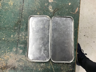
The first move was to figure out the starting shape of the piece of annealed 1mm aluminium that would eventually form the end product.
To do this, a scrap piece of paper was hand molded roughly over the RHS fender section, masking taped in place, and a rough outline of the fender section drawn on the paper in using a marker.


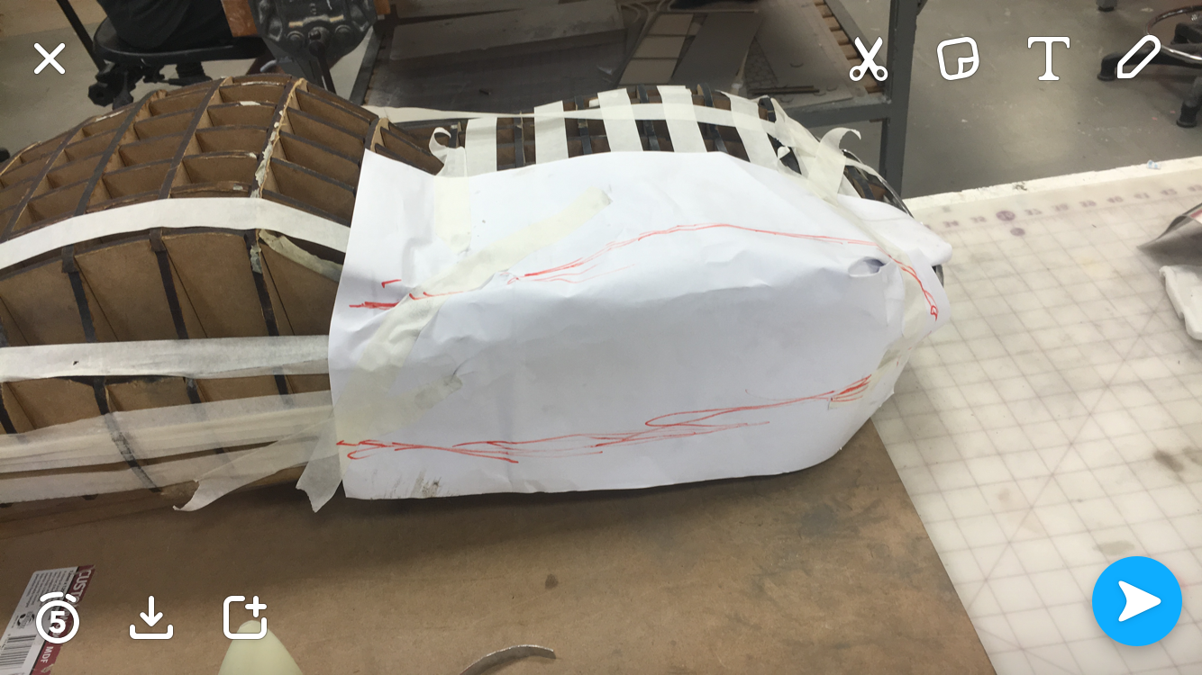
The piece of paper was then un-taped, taken off the buck and flattened out.
The areas that were bunched up represented areas that would require shrinking of the metal.
This paper was then cut out around the marker line, leaving a generous 1-2inch margin.

The paper cut out was then traced onto a piece of 1mm annealed aluminium using a permanent marker.
Tin snips were used to cut out the rough stencil shape that had been marked, and then the aluminium pieces were roughly filed down for ease of handling.
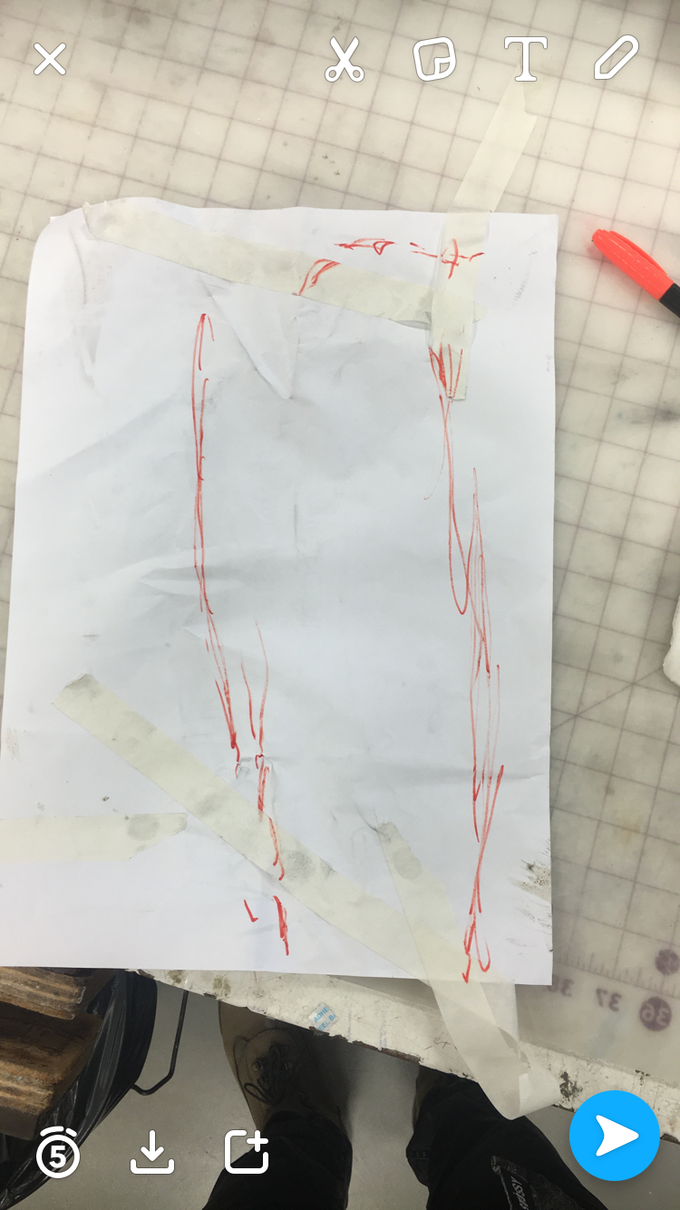
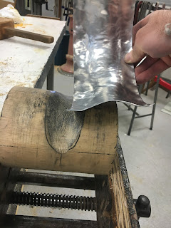
As a starting point for the next part of the metal shaping process, the areas of shrinkage that occurred on the paper were marked out onto the aluminium.

The illustration above shows a couple of the shrinkage areas on the RHS fender section.
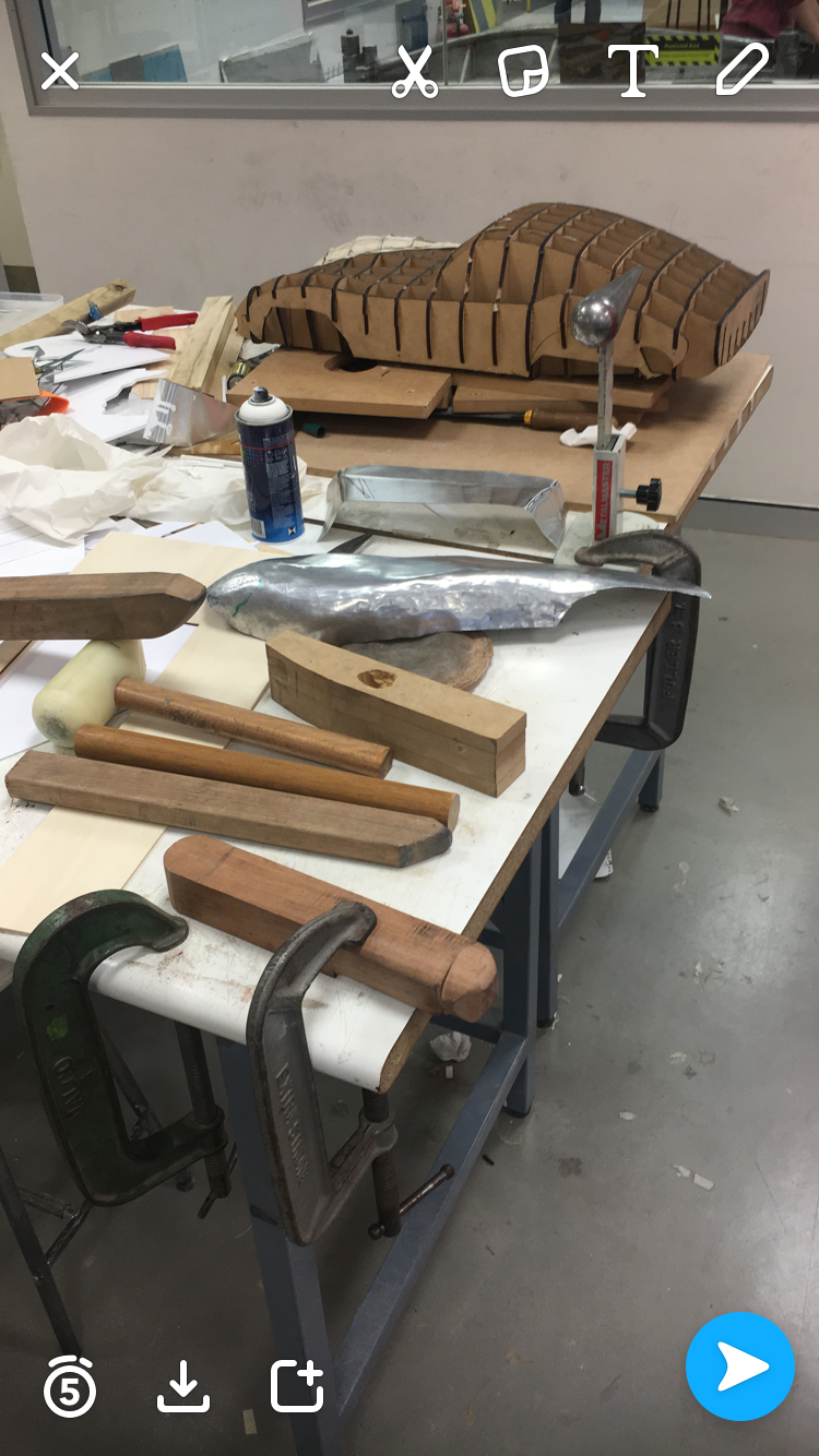
Above: Some of the tools used to shape the aluminium. Note that many tools are basic lumps of wood.

The photo above shows the initial shrinking points to help form the sweeping linear curve of the fender.

Above: A general shape of the fender starts to take place as the top curve is being formed. Note the central flatness, a result of using a flat crowned English wheel to gain the linear consistency.

The above picture shows the end of the fender needs to be shaped downwards and tucked in all together.

The picture above shows that the aluminium skin is starting to tighten up and fit better onto the buck.
further shrinkage in the areas:


Areas that required further shrinkage are formed closer to the buck.

The panel has now been trimmed of excess material using tin snips. The rigidity of the tin snips has caused the panel to buckle slightly, losing the left hand side of the main sweeping curve.

The buckle has been fixed.

After a light sand and polish.


Front view.

Rear view.
After checking the shape by overlaying the panel on a photograph of the Ferrari it was evident that the wheel arch cut needed to be extended.
This process would require scoring the correct line and using the tin snips to adjust the wheel arch.
Reflection
I am currently in my final year of studying a Bachelor of Landscape Architecture. The discipline of landscape architecture is largely focused on how human impact on the environment can be improved in the process of benefiting humans.
As a depth of knowledge on a range of materials is needed to best achieve the desired end product of a project, this course has allowed me to hone in on the material capabilities and restrictions of using sheet aluminium and the effects that the annealing process has on the raw material.
Through the application of the techniques used to manipulate the aluminium, I noticed that the metal shaping process was iterative.
When one area of the material was stretched, it often resulted in another area needing to be shrunk. Continual application of the techniques began to give more definition the the piece through each iteration, there is a strong relationship to the landscape architectural design process as it too is iterative in nature.
Below is a series of images that I found linked the material qualities of aluminium and what I have learnt over the course of the digital making class, with the discipline of landscape architecture.

The picture above is a landscape architectural installation called The Sequence, in Brussels, Belgium by Belgian artist Arne Quinze. The noteable link between this installation, and much of Quinze's other work, is how the use of a rigid material (in this case timber members) are arranged and manipulated to form a piece with visual softness. The timber members have been assembled to form a cloud like structure between the two buildings.

In contrast, the approach to landscape architecture can embrace the qualities of a given material and represent them through the design of hard and soft landscape elements.
Above is General Maister Memorial Park in Slovenia. Here the design outcome could be described as a voronoi in the landscape where sectors are seemingly competing for space. This can be likened to the treatment of shrinking and stretching areas of the aluminium to eventually create a cohesive whole that takes ownership of its form.
Comments
Post a Comment